
Explore what we offer
At our company, we understand the critical role that industrial materials and equipment play in your operations, and we're here to support you every step of the way. Our dedicated team is always ready to provide personalized assistance and ensure you have everything needed to keep your projects running smoothly.


APPLICATIONS
-
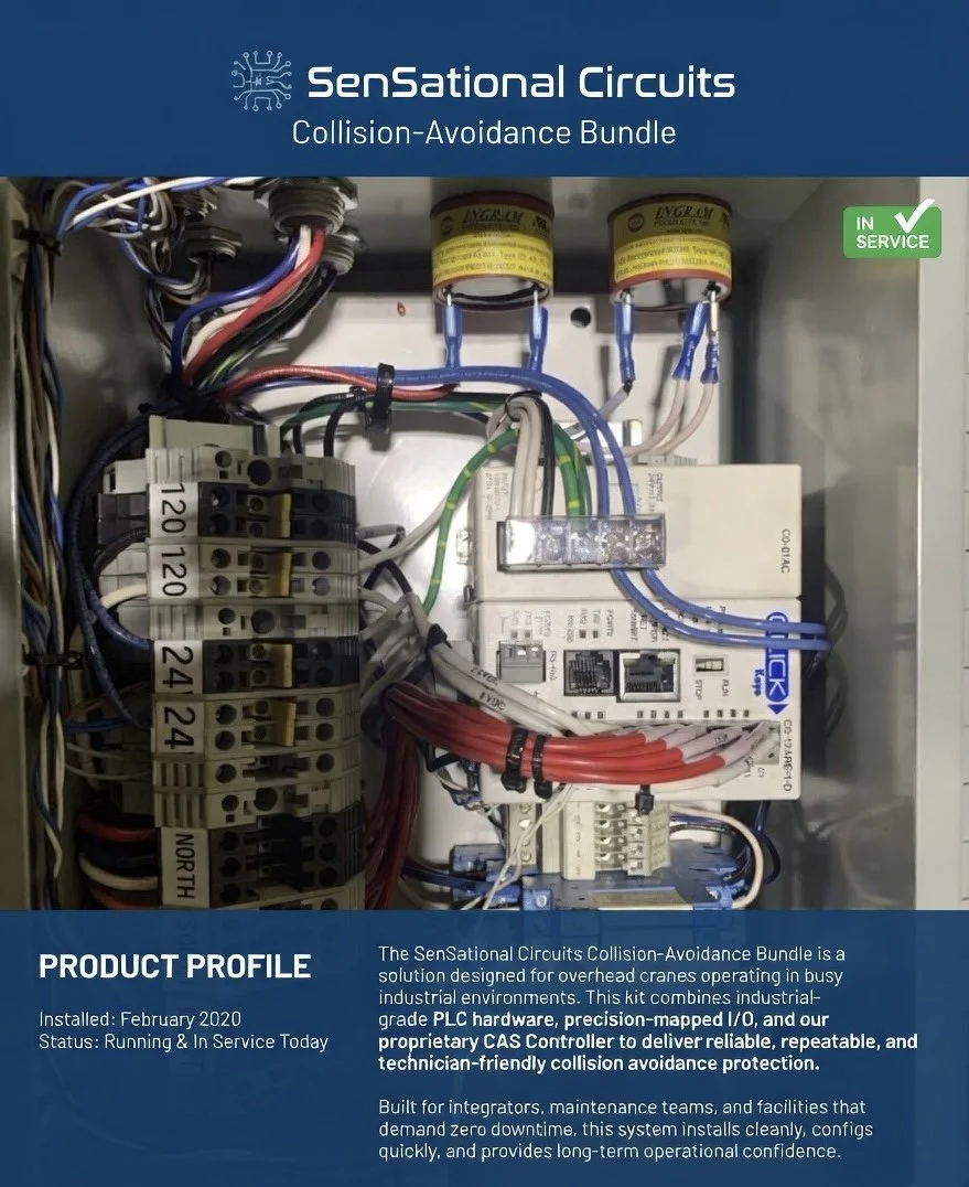
Collision Avoidance
1. Introduction
This manual provides installation, configuration, and maintenance instructions for a Collision Avoidance Setup.
2. Safety Notes
IEC 62061 SIL‑2 compliance requires the use of:
Certified safety sensors
Certified safety logic (e.g., safety PLC or safety relay)
A VFD with Safe Torque Off (STO) or external dual contactors
This guide provides the architecture to support such integration, but is not a standalone certified safety function.
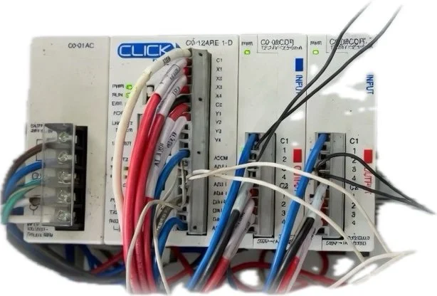
3. Components needed
Controller and distance sensors
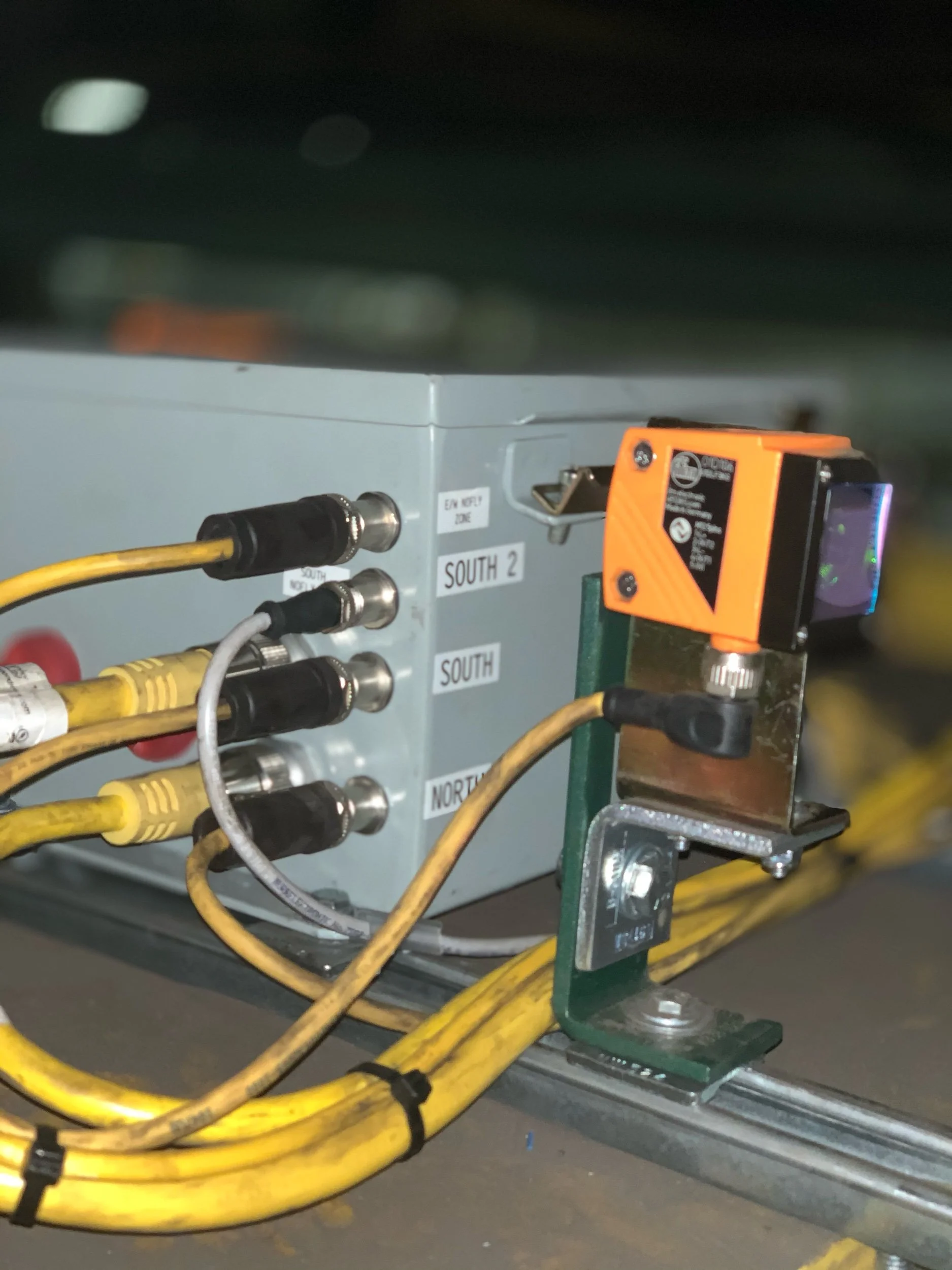
4. Installation Steps
Mount reflectors and sensors using the provided angle brackets and mounting sets.
Connect the sensors to the PCB using the M12 shielded connection cables.
Wire the relay outputs to:
VFD LL1/LL2 and UL1/UL2 inputs, or
External contactor coils for motion inhibition.
5. Configuration Instructions
Use DIP switches to configure each input channel for Normally Open (NO) or Normally Closed (NC) logic.
Implement staged speed removal by assigning relays to intermediate and final limit zones.
Configure directional inhibit by mapping relay outputs to VFD directional inputs or contactor control.
6. Wiring Diagrams
Dual‑channel sensor inputs:
CH1 and CH2 per direction wired to separate input terminals.
Relay outputs:
RLY1 / RLY2 → LL1 / LL2
RLY3 / RLY4 → UL1 / UL2 or contactor A/B coils
Use NC relay contacts for fail‑safe behavior; loss of power or signal opens the circuit.
7. Maintenance and Proof Testing
Inspect sensor alignment and cable integrity regularly.
Test each input channel independently to verify relay response.
Validate relay contact wear and buzzer functionality every 6 months.
Document proof test intervals and results per IEC 62061 lifecycle requirements.
8. Troubleshooting
No relay activation:
Check sensor power, DIP switch settings, and input wiring.
False alarms:
Verify sensor alignment and NO/NC configuration.
VFD not responding:
Confirm relay output wiring and VFD input logic settings.
-
1. Overview
The controller can operate pumps for tank filling, draining, or level‑maintenance using industrial sensors to detect fluid height or presence. Relay outputs provide reliable switching for pump motors, solenoids, or contactors.
2. Typical Applications
Sump pump automation
Tank fill/overflow prevention
Irrigation or nutrient dosing systems
Auto top‑off (ATO) for aquariums or reservoirs
3. Required Components
Industrial level or distance sensor (5‑wire, dual‑output recommended)
Pump or solenoid valve
Relay‑rated power interface (direct pump load or contactor)
4. Installation Steps
Mount the level sensor above or inside the tank.
Connect the sensor to the controller using the M12 or terminal‑block interface.
Wire the pump or solenoid to the relay output (NO or NC depending on fail‑safe preference).
Provide power to the controller and verify sensor operation.
5. Configuration
Assign Output 1 = “Low Level”
Assign Output 2 = “High Level”
Configure relays for:
Fill Mode: Pump ON at low level, OFF at high level
Drain Mode: Pump ON at high level, OFF at low level
Use NC logic for fail‑safe behavior where appropriate.
6. Safety Notes
Pumps drawing more than relay contact rating must use a contactor.
Ensure proper grounding and GFCI protection for water‑related installations.
7. Troubleshooting
Pump not running: Check relay wiring and sensor alignment.
Pump cycles too often: Adjust sensor position or hysteresis.
False triggers: Verify NO/NC DIP switch settings.
-
1. Overview
The controller can actuate solenoid valves for flow control, directional control, or zone switching based on sensor inputs.
2. Typical Applications
Irrigation zone switching
Pneumatic cylinder control
Chemical injection
Cooling water routing
3. Configuration
Map sensor outputs to relay activation logic.
Use NO or NC contacts depending on valve type.
For pneumatic systems, ensure proper pressure and exhaust routing.
-
1. Overview
The controller can activate buzzers, lights, or sirens when sensor thresholds are reached.
2. Typical Applications
High‑level tank alarms
Proximity warnings
Machine approach alerts
Over‑travel detection
3. Configuration
Assign Output 1 or Output 2 to alarm conditions.
Connect alarm devices to relay outputs.
Use NC wiring for fail‑safe alarm activation.
-
1. Overview
The controller can serve as a simple logic interface between sensors and actuators in small automation tasks.
2. Typical Applications
Part detection
Gate/door interlocks
Conveyor indexing
Presence/absence detection
3. Configuration
Map sensor outputs to relays as needed.
Use DIP switches to set NO/NC logic.
Combine multiple relays for multi‑stage logic.
-
1. Overview
The controller can monitor product flow on a conveyor using distance or presence sensors. When a blockage, backup, or jam is detected, the relay outputs can stop the conveyor motor, trigger alarms, or activate diverter mechanisms. This prevents equipment damage, product loss, and unsafe operating conditions.
2. Typical Applications
Packaging line backup detection
Conveyor jam protection
Reject chute monitoring
Pallet or tote accumulation control
Automated sorting or routing systems
3. Required Components
Industrial distance or photoelectric sensor (dual‑output recommended)
Conveyor motor starter, VFD, or contactor
Optional: buzzer, stack light, or diverter solenoid
RM Systems Modular PCB (controller)
4. Installation Steps
Mount the sensor above or beside the conveyor to monitor product presence or accumulation.
Connect the sensor to the controller using the M12 or terminal‑block interface.
Wire relay outputs to:
VFD run/stop inputs,
Motor contactor coil, or
Diverter solenoid valve.
Power the controller and verify sensor alignment and detection range.
5. Configuration
Assign Output 1 = “Product Detected”
Assign Output 2 = “Backup / Jam Condition”
Configure relays for:
Motor Inhibit Mode: Stop conveyor when jam condition is active.
Alarm Mode: Activate buzzer or stack light on jam.
Diverter Mode: Trigger solenoid to reroute product when accumulation is detected.
Use NC relay logic for fail‑safe motor stop behavior.
6. Safety Notes
Motors exceeding relay contact ratings must be controlled through a contactor or VFD input.
Ensure sensors are mounted securely to avoid misalignment from vibration.
For personnel‑accessible conveyors, integrate with certified safety devices (e‑stops, light curtains, safety relays).
7. Troubleshooting
Conveyor won’t start: Check relay wiring and NC/NO configuration.
Frequent false jams: Adjust sensor angle, distance, or detection threshold.
No jam detection: Verify sensor output wiring and DIP switch settings.
Frequently Asked Questions
-
We offer a range of solutions designed to meet your needs—whether you're just getting started or scaling something bigger. Everything is tailored to help you move forward with clarity and confidence.
Manufacturing
Water systems
Collision avoidance
Agriculture
Small automation builders
DIY engineering
-
A collision avoidance system (CAS) is a technology designed to prevent or mitigate collisions by detecting potential obstacles and taking corrective actions.
Key Features •
Collision Avoidance Ready Supports industry‑standard distance, proximity, and optical sensors. Ideal for preventing equipment impacts, monitoring approach zones, and triggering alarms or shutdown sequences.
• Multi‑Purpose Industrial Automation A single controller that adapts to dozens of use cases.
• Supports Dual‑Output Sensors Compatible with 5‑wire industrial sensors (brown/white/blue/black/green‑gray), including IFM, Omron, Pepperl+Fuchs, and other major brands.
-
Our team is united by a shared commitment to building reliable, practical, and scalable industrial automation tools. We’re driven by the belief that smart, well‑designed control systems should make real‑world operations safer, simpler, and more efficient.
-
We offer flexible pricing based on project type and complexity. After an initial conversation, we’ll provide a transparent quote with no hidden costs.
-
Collaborative, honest, and straightforward. We're here to guide the process, bring ideas to the table, and keep things moving.
Team Culture
Our team thrives on practical innovation, clear communication, and a shared commitment to building solutions that genuinely make industrial work easier and safer. We value hands‑on problem‑solving, continuous improvement, and designs that put real‑world users first. Collaboration, curiosity, and a drive for reliability shape everything we create, from early concepts to field‑ready hardware.
-
Start With the Process, Not the Hardware
Automation succeeds when it’s built around actual workflow behavior, not theoretical diagrams.
Map the process:
Inputs → transformations → outputs
Cycle times and takt time
Variability (batch size, operator differences, environmental factors)
Pain points (errors, delays, safety risks)
-
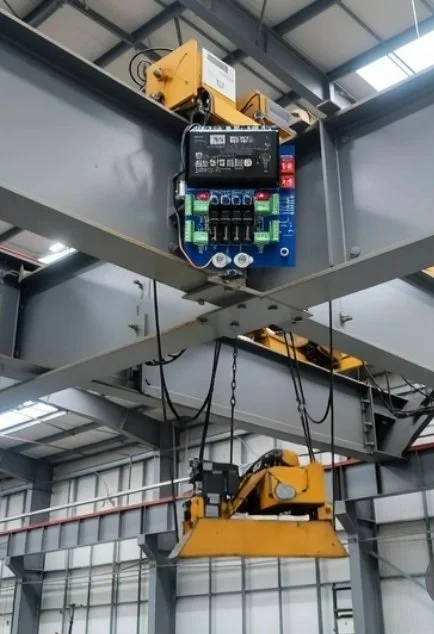
Industrial environments are getting faster, more automated, and more crowded. Whether it’s forklifts navigating tight aisles, cranes moving heavy loads, or AGVs running predictable routes, collision avoidance systems have become essential for safety and productivity.
But the heart of every collision avoidance setup is the controller — the device that reads sensors, makes decisions, and triggers alarms or shutdowns. Choosing the right controller can dramatically improve reliability, reduce downtime, and simplify integration with existing equipment.
This guide breaks down what to look for, compares leading brands, and explains where modular controllers like those from SenSational Circuits fit into modern automation.
What a Collision Avoidance Controller Actually Does
A collision avoidance controller acts as the logic brain between sensors and equipment. Its job is simple:
Monitor sensors such as radar, ultrasonic, LiDAR, photo eyes, or UWB tags
Process distance, speed, or presence data
Trigger alarms, slow-down signals, or relay outputs
Protect operators, equipment, and inventory
A good controller must be fast, reliable, and compatible with the sensors used in your environment.
Key Features to Look For
When evaluating controllers, focus on:
Sensor Compatibility
Ultrasonic
Radar
Photoelectric
LiDAR
UWB proximity tags
Loop detectors
Response Time
Milliseconds matter — especially for moving equipment.
Environmental Durability
IP ratings
Temperature range
Vibration resistance
Electrical noise immunity
Integration Options
Relay outputs
PLC inputs
24VDC logic
MQTT or network reporting
Compatibility with VFDs, contactors, and safety circuits
Modularity & Expandability
Future-proof systems save money long-term.
Why Modular Controllers Are Becoming the New Standard
Traditional PLC-based systems work well, but they’re often:
Expensive
Overkill for small applications
Hard to scale
Locked into proprietary ecosystems
Modular controllers solve these problems by offering:
Plug-and-play sensor inputs
Simple relay outputs
Clear diagnostics
Field-replaceable modules
Lower cost of ownership
Easy integration with existing equipment
This is exactly where SenSational Circuits fits in.
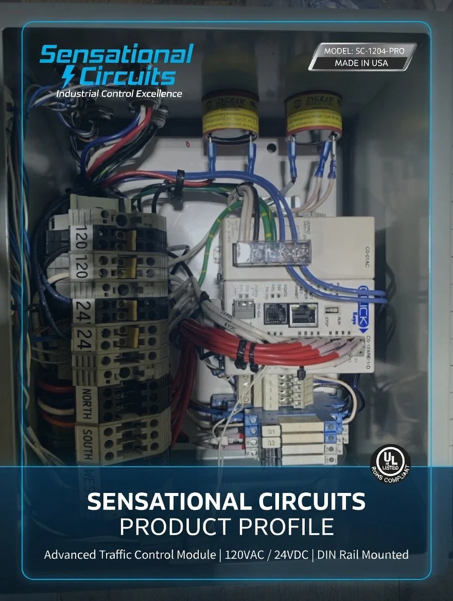
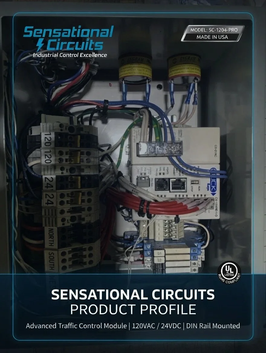
SenSational Circuits Collision Avoidance Controller
SenSational Circuits provides a compact, modular, sensor-agnostic controller designed for real-world industrial environments.
Highlights
Works with ultrasonic, radar, photo eyes, and more
Clean relay outputs for alarms, slow-down, or shutdown
12–24VDC operation
Rugged connectors and clear labeling
Designed for technicians, not programmers
Perfect for small manufacturers, automation builders, and custom machinery
Contact us
Interested in working together? Fill out some info and we will be in touch shortly. We can’t wait to hear from you!